The learning curve required a paradigm shifted in abstraction. That was too much.
I just want OpenSCAD simplicity, but with modern programming language syntax.
I ended up settling with PythonScad. I was able to hit the ground running and leverage what I already know about python within a day.
It's new, but the author is extremely active and collaborative on github (https://github.com/gsohler/openscad) and reddit (https://www.reddit.com/r/pythonscad/). The author actually pushed for merging this into OpenSCAD mainline, but got gatekeeped out since OpenSCAD maintainers believed Python went against OpenSCAD's mantra of being 'secure'.
I recommend PythonSCAD to anyone that liked OpenSCAD simplicity in abstraction but feel handicapped by the lack of expressiveness.
This is true! And I think that brute-force simplicity of OpenSCAD is the appeal. I am still ultimately a CAD greenhorn but it got me started, and I don't blame you.
But I guess the point I am getting to is, that paradigm shift is where you really want to be. It's certainly where I think most competent programmers who want to really build in 3D should want to be.
Because it unlocks the ability to reason about the shapes you're creating, within the code that creates them. You can for example place a feature in the centre of a face of an object you just created, without having to recalculate the location of the centre of the face or the normal etc.
You can write code that is truly parametric with real encapsulations, and without a battery of variable definitions and calculations for every single element -- because you can reflect on what you've already made.
(You can also export STEP files to other packages, import STEP files and reason about/analyse those as objects rather than meshes.)
Perhaps someday, but I havent had the need to get there thus far.
Also: Encapsulation etc was achievable with Python, which is something I already know. PythonSCAD checked all the boxes for me without the learning curve.
But openscad is a cool and minimal instruction set for such experiments, and doing this in a language with better meta programming support would be even more fun.
https://web.archive.org/web/20211123185332/https://wiki.shap...
I really hope that OpenPythonSCAD becomes standard and that it can harness all that energy and creativity --- in particular note that it is now possible to upload a design for sharing using it.
> Because it unlocks the ability to reason about the shapes you're creating, within the code that creates them. You can for example place a feature in the centre of a face of an object you just created, without having to recalculate the location of the centre of the face or the normal etc.
I can definitely see the appeal of this; would it be possible to refit such capability back into OpenSCAD's model (even if it meant breaking some backwards compatibility)? Like, you're not just executing imperative "drawing" operations, but the models you've created become available as first-class objects to be further referenced & poked at?
This is where my understanding gets weak, but I think the answer in a practical sense is no. Not with the way that kernel works. It could be somewhat modelled on top, but then you have a layer around the kernel doing essentially the whole task of a bRep kernel.
You will discover these problems while still green, and their report is corroborated by anyone else who has used openscad.
You could try it yourself and discover that what they said is true.
If you've tried to use openscad to model more than a cube, then you have run in to the limitations. If you have gone on to spend years building models in openscad, then you know even more limitations and problems than you did while "green".
Even people like myself who use openscad for as much as they can because they love being able to describe an open source model in about 1k of human readable, editable, parametric, gittable text instead of several megs of xml or binary, even we will say that this is all simply true. the more experienced you are, the more you know how true it is.
I will still call myself green because I will simply call myself green about almost everything as simple facet of my character, regardless how many years or how much work I've done with something.
Should such people not advise others on what they have learned? Do self-proclaimed experts largely give better advice than experts, or even mere practitioners, who don't like to self-aggrandize?
Regardless, in this case their statements were all sound. As someone who has spent a lot of time figuring out methods to get things done that a new user would not know yet, I have no notes on this greenorns opinions.
The point for me is that, as a relative novice, I have got past some really important hurdles recently. So I can explain the benefits of getting past them to people who maybe don't know they are there.
I started off using OpenSCAD because it convinced me I'd be able to make something, quite quickly. My first two or three things were OpenSCAD things. It introduces you to stuff that isn't immediately obvious: the more complex booleans like difference of simple primitives, extrudes, lofts, sweeps, revolves. Great! I made things, I printed them, it was transformative.
(There's also quite a good thread library -- Adrian Schlatter's threadlib -- that I do want to say is very helpful and I learned a lot from.)
But it will likely hold back your development as a CAD user for even modestly complex things. Because you will never get access to the fundamentals of your objects -- the faces, vertexes and edges. Putting aside BOSL and the like, it leaves you stuck with a lot of increasingly complex maths, when if you could use the generated geometry you would not have to be. You would have much simpler operations relative to faces and edges.
This is why I said it would be worth spending at least some time with these tools. So you know what is out there.
Say for example a single six-sided die: six faces, twelve edges.
But this would be twelve mesh triangles, right? None of which individually represent a face -- and six of the mesh edges are not edges in the true geometry.
A rounded six-sided die might have 26 faces (including the curved edges, rounded corners). 48 edges between them. etc. But the number of mesh triangles and edges will vary according to the precision.
bRep kernels can give you the geometry information, not just the mesh information.
IIRC STLs are triangular meshes. Would bRep programs like build123d able to "convert" them to "true geometric objects"?
I would presume the answer is no.
You can make an almost perfect analogy with raster and vector image formats. They both have their niches; however: it's trivial to rasterize a vector drawing, but it's a ton of work to vectorize an raster image well.
So, all things being equal, it makes sense to start your designs at the 'high ground'.
Right. OpenSCAD can import and mesh STEP files. But the process throws away the true geometry.
I agree that the raster/vector analogy is strong!
Plasticity (the sorta-CAD-sorta-modeller app) has seemingly just added some logic to the recent version to help with extracting the true geometry from meshes. I want to like Plasticity but it's not enough CAD for me right now.
however, openscad does not have an internal B-REP kernel and you would have to rewrite the program to change that.
https://github.com/derkork/openscad-graph-editor
see:
https://raw.githubusercontent.com/WillAdams/gcodepreview/mai...
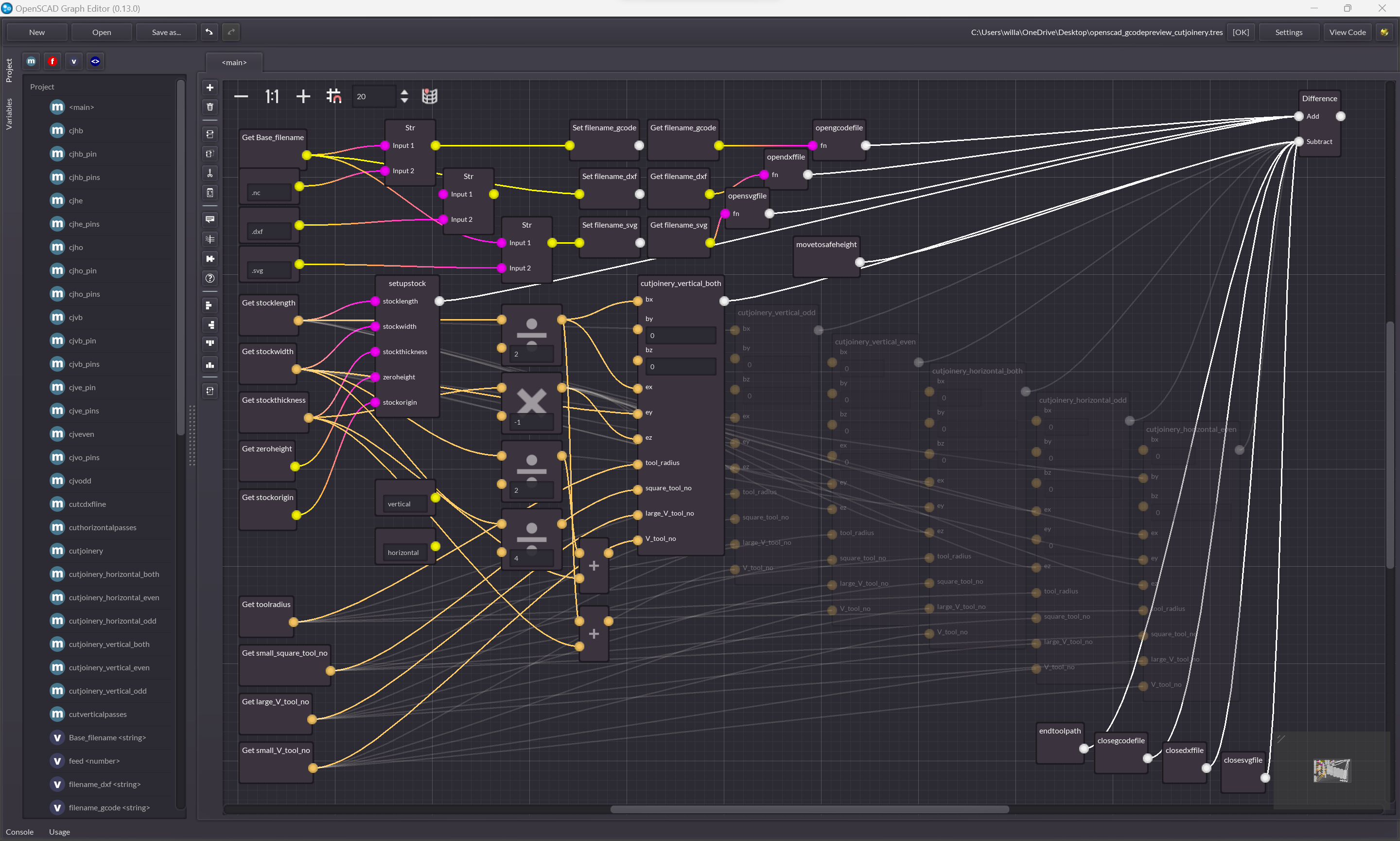
and the matching:
https://raw.githubusercontent.com/WillAdams/gcodepreview/mai...
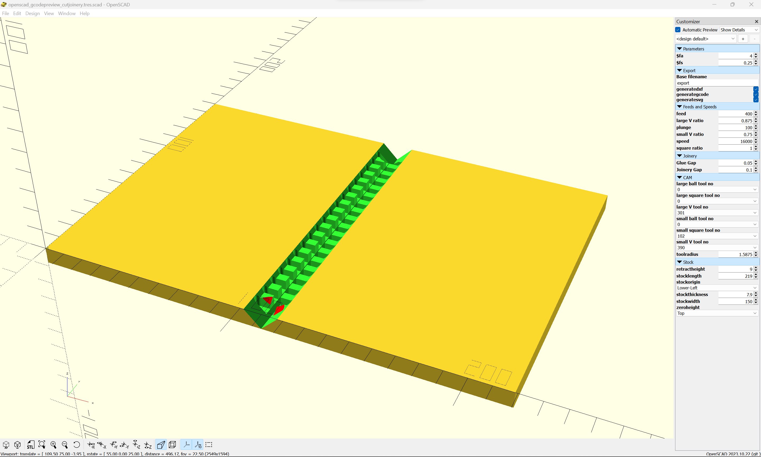
But that said, this is all correct. OpenSCAD is actually an extremely limited environment and much more expressive tools exist in the same "code-based 3D modelling" space.
I saw this thread only because it's clearly a followup to the FreeCAD discussion the other day that I have contributed to.
--
People do get oddly grumpy when you criticise OpenSCAD; there is an element of the "I can do maths and refuse to believe CAD needs to be any more than this" militancy about it.
I absolutely don't hate it -- OpenSCAD's mere existence is what unlocked my ability to even reason in 3D, actually. But that quasi-militant tendency is holding back a fascinating, liberating software field.
https://www.goodreads.com/book/show/58059196-make
which has since become a series including:
Trigonometry: https://www.goodreads.com/book/show/123127774-make
Calculus: https://www.goodreads.com/book/show/61739368-make
Currently working through a library using the new Python-enabled OpenPythonSCAD, and at the end of it, hope to work on a project which requires conic sections (which I'm still researching, so if anyone has any good resources on that I'd be glad of them).
Joan Horvath is a superhero -- I've seen a few interviews now.
I will very happily use OpenSCAD for that because it seems like a well-chosen tool for the job.
Most of us don't realize how much our comfort with familiar concepts affects our ability to objectively evaluate them. Moving from dev to being a tech artist, I see the same exact sort of irrational biases, hang-ups and endemic misconceptions with completely different tool chains and types of complexity. When I first started using Houdini, I tried to turn every task into a Python coding problem because that's what I was comfortable with— Python is amazing in Houdini but it's definitely not the best way to accomplish most tasks.
The awful thing about OpenSCAD is that what one can create in it is strongly bounded by one's facility with and fluency in mathematics.
I'm curious how the new Python-enabled (I really hope it gets added in to the program itself) will affect this.
https://github.com/WillAdams/gcodepreview
See:
https://github.com/WillAdams/gcodepreview/blob/main/export.d...

Have you looked at grblgru.com ? Not opensource, but does have CNC lathe support.
I do not have any DXF of something like this.
As an example, if doing V carving, the appearance will be smoother if the geometry is imported so as to have arcs/curves, deferring the conversion to polylines/straight line movements until the last possible moment on the machine.
Arcs/Curves are also easier to work with if one needs to edit, and are more efficient in terms of representation/disk space/storage.
CAM people, for example drive numerically controlled machines and robots. (CNC machines) These machines are driven by lines, arcs, higher order analytic curves, such as the conic, and recent controllers will accept bsplines.
Having path planning done with real geometric entities brings a lot of benefits along for the ride! Accuracy without a bazillion entities for the look ahead system to manage and for program buffers to drip feed (DNC) to a machine that probably does not have a large enough program memory to deal with that bazillion entities.
In many cases, derivative or extrapolated curves do not convey the right shape or path or are difficult and time consuming to force conformance.
We ended up with the big geometry kernels, such as Parasolid, precisely so that CAD could create a brep (boundary representation model) of sufficient fidelity to make other tasks, such as CAM and simulation, as well as derivative designs possible, practical, repeatable.
Those big code bodies have so damn many man hours of development in them it is very hard to replace it all. And that means we are stuck with some things, like many operations being single threaded, which caps CAD design to be a function of sequential compute speeds.
There are ways to build models to eliminate some dependencies, and the same goes for assemblies, so that multi-processing of some sort is possible. That brings our multi-core CPUs into the game.
But those are hard to teach, a lot of software does not yet support multi-threading anywhere near enough to fully exploit the model work, and, and, and...
In the CAD / CAM world, the primitive is the b-spline, and the surfaces it can represent.
Those generate faces, trim boundaries and sets of those create boundary representation models.
And still those can cause grief. They might be open, or just a surface representation. Or, they may self intersect...
Basically, every edge, which boils down to a b-spline curve that matches up to another b-spline curve serving as a trim boundary of a surface, must be shared by two and only two surfaces or the model is not representative of a real world, manufacturable thing.
Another great observation regarding real world objects is there are no edges, just radii, if only a single molecule big. Just an interesting and perhaps useful aside.
And b-splines are constrained to conform to the properties of lower order entities, such as lines, arcs, and the like. This is a part of why wireframe entities are all called "curves" or "sketch curves." They literally are all b-splines constrained by number and or placement of control points.
This doesn't work if you already have a mesh. You need to generate your triangles on demand from the BREP data.
Alternatively you need to use tesselation, but then you need to design your models with tesselation in mind, such as people do in blender.
>Isn't this how any rendering will ultimately work? The primitive is triangles.
Uhm no. 3D printing and CAM do not work with triangles. The slicer and CAM software generate tool paths in gcode.
Importing STEP files into OrcaSlicer/BambuSlicer gives me better quality results and better print speeds than using STL files.
I have personally never understood the love for STL files in the 3D printing community for anything that isn't the result of a blender export. Like, is it really that fun to constantly export different versions of STL files set to different quality levels? Rescaling a print in the slicer is not recommended with STL. You have to re-export the model from blender where the tesselation happens.
[0] Some will import them now but convert them to triangles, cura can use a plugin to convert those triangles back to G2-G3 arcs or circles.
[1] at least by default, marlin has optional support for arcs that can be enabled at compile time.
OpenSCAD also has a lower barrier to entry in that the programming language and environment is familiar without needing a lot of training or context.
(With the addition of developer openness: directly meshing with Python or JS libraries)
This is why such a basic-seeming thing as “how do i get the bounding box for this CSG frankenobject I’ve created?” comes up again and again on stackoverflow etc. it’s apparently not possible without some hacks.
I’ll take a look at the alternatives you mentioned, thanks.
BUT
for these reduced price options, it's the educational version, and the files are watermarked, and the license precludes commercial use.
That said, if your goal is to learn a CAD program and get a job --- in an industry/region which uses Solidworks_ (for some reason, CAD usage seems to be specific to either certain industries or regions, though SW is almost certainly the most widespread), that is definitely the way to go, along with a Community College course/degree and/or a training certificate:
Is commercial use allowed?
It’s like programming without higher level language constructs. Yes, lower level languages are still Turing-complete so can technically do everything. But the necessary housekeeping distracts from the real problem I’m trying to solve.
Not saying it's not possible - I've seen what it can do - but even with my software background it was hard for me to really work with something that isn't based on constraints.
CadQuery may appeal to you? It does have (some) early support for constraints in 2D and 3D I believe.
(CadQuery and Build123D ultimately share both OCP underpinnings and viewer tooling.)
Personally, I rather like the constraint based approach in FreeCAD and miss that a lot in OpenSCAD.
I am sure you are right that this is still the case. This is a big plus for OpenSCAD.
One of the alternatives I mention takes customisation to a different level that makes me hopeful.
Replicad can be used as a library in a web app:
https://replicad.xyz/docs/use-as-a-library
And they have a demo here (a React app):
There was a very short attempt at starting to make a GUI for truck [2] but development has seemed to have halted. There was discussion and hype about this here a couple months ago [3].
[1]: https://github.com/ricosjp/truck
If that doesn't exist, why not?
(N.B. the Replicad studio code editor on that site seems to be broken today, which is a bummer -- it wasn't when I last checked)
CadQuery might not be in Ubuntu repositories on its own (same with Build123D -- these are python libraries really) but have you tried looking for cq-editor? (I think that's in Homebrew as well.)
https://snapcraft.io/install/cadquery-editor/ubuntu
To be fair I'd probably install the VSCode support for Build123D and CadQuery instead, because 1) this is code-CAD and you really manage it as such, and 2) I'm not that fond of the cq-editor environment.
https://marketplace.visualstudio.com/items?itemName=bernhard...
https://github.com/bernhard-42/vscode-ocp-cad-viewer
This extension can install Build123D or CadQuery for you if you have a python setup for VSCode.
And appears now to be fixed.
[0]https://www.fornjot.app/ [1]https://github.com/hannobraun/fornjot
May 2023 https://www.fornjot.app/blog/a-new-direction/
I don't know how things will shake out long-term, but for now, I'm going to reduce my effort to one day per week...
As of now, the goal of Fornjot is no longer to build a CAD application. From now on, Fornjot is a CAD kernel...
Last week: https://www.fornjot.app/blog/changes-to-the-development-proc...
There will be no more releases for the time being.
I will no longer submit pull requests for my own work.
I make models for my 3d printer just a few times a year. I find it much easier to get back into openscad than remember my way around a gui or wrestle with more advanced tools.
There's nothing I've not managed to make with openscad yet, though the things I have made are embarrassingly simple (yet highly functional).
It is workable if you have an extremely solid grasp of mathematics, and you don't mind objects that ultimately retain the feel of the combination of a few CSG primitives.
But I make 3D-printed things that for a variety of reasons are little more than rings, plates, discs, and helixes, and I've already very clearly run into situations where the face/vertex/wire model of a proper CAD package is more or less the only way to keep control over a design.
All my models are about 50% variable declarations and 50% inscrutable equations to express the relationships between the values. Sometimes huge ternary stacks because the language doesn't allow variable changes, so you can't have simple if/else/case to have a simple concept like a default value that maybe gets replaced based on some other condition.
And the lack of things like fillets is simply impossibl. The things you have to do to attain the end result of a fillet without an actual fillet function is ridiculous, and even after doing the ridiculous things, you still have a limited crap result where no matter what you simply can't actually have a fillet wherever you want, but you can compromise and get at least the ones you really need if you're willing to live with a simple design.
That is not a good tool. A good tool gives you the means to express whatever you need to express. Openscad gives you the power to express cubes and spheres and hulls and intersections of those, and even that only in a bafflingly limited way thanks to the language limitations.
It's not a great tool. It's a great proof of concept for a great idea for a great tool.
I think there's an opportunity for a code-first CAD API to incorporate GD&T and manufacturability information directly as part of the modeling process. For example, if I'm making a shaft I want to describe that operation as it will actually be performed in the shop e.g.:
  (1) select round stock of nominal dimension X
  (2) cut to rough length
  (3) chuck in 3-jaw chuck and drill center
  (4) flip around in 3-jaw chuck and drill the other center
  (5) mount between centers
  (6) turn to rough outer dimension
  (8) turn down to add the various bosses, threads, chamfers, other details, etc...
So I think these APIs are coming at the problem from the wrong point of view--they're all about driving the CAD kernel and telling it how to draw abstract shapes in a computer. Instead what I want is to tell the computer how I intend to make the thing and get an estimate of what the result will look like.
I have certainly learned over time that when you're looking at an object that exists in the real world, one way to start to figure out how to model it is to figure out how it -- or its injection-mould positive -- was physically made. Can it be cut with a mill? Was it glued together in parts?
It absolutely is fun to try to work out how to come up with a shape subtractively from some giant primitive as if it was a block of steel. I often find myself visualising in terms of a scroll saw. I watched a couple of great videos about three-dimensional scroll-saw work and it weirdly affected my understanding of CAD!
The problem of course is that that limits one to straight lines and arc moves.
Are there any really good G-code previewers for lathe work?
For that matter, what is the best 3D G-code previewer which will allow one to see the surface of the cut part in 3D? I'm about to break down and buy tkcnc --- is there something better?
No, I think G-code is too prescriptive and low level for the modelling task. What I'd prefer is some way to specify operations in a fluent, object-oriented API e.g.:
  round_bar = RoundBar(
    alloy=1018,
    diameter=Dimension(1*Inch, error=0.010*Inch),
    length=Dimension(12*Inches, error=0.25*Inch)
  )
  3_jaw = 3JawChuck(tolerance=0.005)
  between_centers = BetweenCenters()
  center_drill = CenterDrill(size=4)

  shaft = round_bar
    .chuck(configuration=3_jaw)
    .drill(bit=center_drill, depth=Dimension(0.250*Inch, error=0.02*Inch))
    .unchuck()
    .rotate(axis=Y, degrees=180)
    .chuck(configuration=3_jaw)
    .drill(bit=center_drill, depth=Dimension(0.250*Inch, error=0.02*Inch))
    .unchuck()
    .chuck(configuration=between_centers)
    .face()
    .turn(
      target_diameter=Dimension(0.750*Inch, error=0.001*Inch),
      length=Dimension(11.5*Inch, error=0.05*Inch, anchor=round_bar.tailstock_face()),
      finish=Rough
    )
    .external_threads(
      class=ThreeA,
      nominal_size=FiveEighths_18,
      length=Dimension(1.25*Inch, error=0.020*Inch, anchor=round_bar.tailstock_face()),
      reverse=False,
      relief=DefaultRelief(FiveEighths_18)
    )
...Something like you propose might be an interesting thing to explore for creating CAM posts. The actual Gcode that your API would emit is going to vary quite a lot even within super-similar machines -- a 3+1 axis job targeting a machine with a FANUC controller is going to be pretty different from the same job targeting a machine with a Heidenhain controller.
I think you might have a point here, but I'm going to push back on the idea that these three parts are the "same part" because they'll all have wildly different mechanical properties, dimensions, and dimensional consistency. They are not all necessarily interchangeable (although they could be, we'd have to integration-test them in an assembly to find out!).
My point is the "abstract part" isn't really a thing, and the real life characteristics of each concrete part are inextricable from the way it's made and what it's made of. I wonder if it would be helpful to force me, the designer, to think about it that way from the start?
3D printing is an odd case that tbh I hadn't really thought of. The things I make are all subtractively manufactured (except for welds which are addictive only in a degenerate sense), and I have no experience with 3D printing.
Perhaps I just wasn't fully understanding how to use it and it wasn't supposed to be mainly CSG focused, but it ended up being much more effective for me to spend a day just fiddling around in FreeCAD to learn how to use it.
(The programmer in me would love to be able to leave comments in more places on FreeCAD designs. I have spent a lot of time trying to learn how to make the simplest, most self-documenting parametric flow.)
But the reason I framed my comment above in terms of spending at least some time with CadQuery or Build123D etc. over OpenSCAD, is that CadQuery taught me additional CAD concepts that helped me make progress.
I had tried to use FreeCAD before, about 18 months before I finally got my 3D printer, but I was absolutely bamboozled. So when I finally started with my 3D printer, I started with OpenSCAD. I got small stuff done and held it in my hands, but I immediately felt its limitations (partly because I struggle with co-ordinate spaces and maths). Was I really going to be stuck doing all the maths, over and over again, or using libraries of specific functions like BOSL? My maths skills are weaker than I'd like, and it felt like a dead-end.
I stumbled on CadQuery, spent some time working on some key things in it, really immersed myself in the documentation, and this helped me grasp the bRep fundamental ideas of faces, vertexes and edges, normals, orientations, planes, etc. All the higher-order concepts in modern CAD above CSG.
I then had two things I knew could work for me -- CadQuery or in a pinch OpenSCAD. And because as you know there are/were workbenches for both, the knowledge gave me the confidence to spend time with FreeCAD.
Without stumbling on CadQuery I would have been stuck with OpenSCAD and it may have driven me away from trying to make my own things.
There are elements of my designs I will be (re-)building in Build123D to get some code-CAD advantages (scripted customisation). But it's the time with CadQuery that helped me make the transition to CAD thinking.
But as a hobbyist, this is the tool I have turned to time and again for making simple parts or objects. I found this to be more intuitive and easier to onboard vs. learning different visual designing tools each with its own quirks.
So it definitely has a place in my toolbox as is.
And you're right it has a place. I'm not totally advocating switching if it works for you. But for newer users who want to really use code-CAD, out there are tools that are not held back by OpenSCAD's limitations (and which scale less painfully with complexity), and learning about them might help see simpler solutions or even bridge the gap to GUI CAD.
The most significant limitation I can see for a hobbyist maker is reaching the point where you can't make something yourself (or can't make it cost-effectively) and need to get it fabricated elsewhere. That is when you may very well find you would benefit from something OpenSCAD cannot (ever, I think) do: true, efficient STEP export.
As my 3D printed designs get more complex I am pushing closer and closer to the point where I will need a part cut conventionally out of steel or aluminium, or -- most likely sooner -- where I will need custom fasteners. One of the advantages of a workflow that will produce STEP is being able to work with someone who has those specialisations (and/or import work into the software tools they use). So at the earliest point I could, I made sure I was in that world. As a side bonus, it means being able to potentially use home CNC, or even just extract vector faces from generated models for use with a laser cutter or a Silhouette-type machine.
Out of completeness I should note that in that situation you're not totally out of options, as FreeCAD can interpret OpenSCAD in a bRep context with the exception of a few operations like minkowski() that get left as meshes. But it's a real limitation.
As impressive as NopSCADlib and BOSL2 are (and OMG they are, when you consider what they have to work with!), OpenSCAD is a one-way, declarative CSG environment that essentially only outputs mesh formats. It's really not that much better than working with three-dimensional pixels. You won't really be able to analyse, iterate over or measure your models, easily build on faces, do easy chamfers or fillets, export STEP files, make use of constraint-based designs, model assemblies, or so many other things that "CAD" means in the 21st century. All the tools that help you do this on OpenSCAD are layers and layers of task-specific hacks and clever bodges.
I totally get wanting to make models with version-controlled text files instead of GUI CAD (which can be a sort of weird battle to learn for a programmer), and I get wanting to avoid FreeCAD. I just don't really get wanting to limit oneself to such a limited concept of a 3D "model"!
The three alternative systems I mention are all based around bindings to (or in Replicad's case, cross-compilation of) OpenCASCADE, which is a bRep CAD kernel capable of much richer interactions. It is not without its faults, but arguably code-CAD spares you from some of the inscrutability that trip up FreeCAD's interactive model.