This only works with perfect resistors, though. If your actual resistors have a fabrication tolerance, you might be more off. For example, if you need a 41 Ohm resistor, you can use a perfect 47 Ohm resistor from the E6-series, and you'll be within 20% error. However, if that 47 Ohm resistor has a 10% fabrication tolerance, in reality it might be 51 Ohm, and that's more than 20% off from the 41 Ohm you needed.
To take the example from the author's last paragraph, if you need a 70 Ohm resistor, the idea is not that you could be lucky and find an exact 70 Ohm in your E24 resistor set, but that you change the design to use a 68 Ohm instead, and don't introduce more than 5% off by doing so (regardless of the resistor value you needed).
If you know what you're doing a 50 cent opamp will give you results that are beyond what a human could identify in a double-randomized blind test. Same goes for comparing two rusty pieces of wire against highly pure copper speaker cables.
For some reason audiophiles will use darn massive gold (or silver) RCA connectors instead of something like a balanced connection that would actually make sense.
For audio applications 1% resistors are fine. You can use still affordable 0.1% in places where you truly care. Below that it is getting ridiculous, as the influence of harder to match things will take over. Things like speakers or the room they are placed in. How about the speed of sound changing with air temperature and humidity? You better have a room that has uniform and stabilized air temperature and humidity.
A big part of the audiophile game is about psychological impact and the joy of personalized optimization. I spent a lot of money on audio equipment and a lot of time on researching it myself. It is an interesting thing. But in the end it is also physics that are interpreted by your brain and I can't help but feel bad for people who need to (incoming hyperbole) turn every part of their setup into gold in order to be able to enjoy listening to their equipment as music passes through it.
It's hard to find XLR (or even TRS) balanced connectors on most non-professional (=TV studios, expensive conference room setups, DJs/clubs/similar venues) equipment.
Yeah but who outside of people already interested in DJing buys that kind of stuff. It just looks ugly, unlike your classic home theater setup.
Out of "looks decent (=passes the Spouse Acceptance Factor test)", "reasonably affordable" and "has decent quality", choose two... unless you got a partner accepting you literally putting up a 2m truss with lasers, movingheads and a strobe in your living room that could compete with a mid-range disco, and a 1.200W fogger on the ground. I'm lucky enough to have such a partner, but I'd say about 99% of people don't.
It is perfectly possible to build beautiful balanced equipment.
Balanced outputs have nothing to do with the aesthetics of the object. And I choose option 4 — build it yourself — then it can be done cheap and look however decent, massive, invisible, ridiculous or whatever the aesthetical ven diagram between your second half and you looks like. And it can have balanced I/O if needed ; )
The truth is that we sound engineers who use that stuff for work often do not have the luxury of caring for things that don't matter to the process or the outcome.
Professional AV equipment is expensive because it needs to be reliable on top of sounding as if it wasn't there, one of those units described above was running without fault for 15 years 24/7 in a room that was 30°C each summer (and it still works). Meanwhile my brother bought a silver RCA connector that broke off after a year of use — tip stuck in the amp, guess who had to fix it..
Is there a reason why they don't just use digital audio everywhere and convert to analog as late as possible? Inside the speakers for example? I mean, digital audio is pretty much perfect. Why are analog audio signals still a thing? People actually pay thousands of dollars for magical analog audio cables and it boggles my mind.
Stepping back for a moment… you see digital interconnects in high-end pro audio gear, using systems like Dante. These systems are NOT simple. When you have multiple digital audio systems connected together, you have to worry about whether they are all running from the same clock, or whether you can convert from one clock to another. Systems like AES solved this by having “word clock” running on separate coax cables with BNC connectors.
If you look at consumer digital audio stuff, like Bluetooth speakers, you find all sorts of weird problems. It turns out that for cheap consumer gear, you get better quality audio from simple analog connections anyway.
If you want speakers with digital inputs, you also need to power those speakers. That uses up more power outlets.
There are a lot of different parts involved—D/A converters, crossover networks, and amplifiers. Back in the day, good D/A converters were expensive, but they have gotten really cheap. If you have amplifiers that are cheap enough, you can put them after the crossover network and save money on the crossover network. If you have D/A converters that are cheap enough, you can eliminate the crossover network entirely and do it in DSP.
At that point you are comparing the cost of one more channel of D/A against the cost of an electronic crossover. It’s super easy to just buy a D/A with more channels. If you get to completely eliminate an analog crossover network, maybe that’s a win in terms of BOM cost.
Many modern Studios run some form of digital audio network as well (Dante, Ravenna, etc) so you can go digital as early and close to the source as possible and do all the routing using network switches and some sort of managment software (e.g. Dante Domain Manager). So if you do that it makes sense to go digital all the way to the speakers and convert directly to analog there after running through a DSP that allows you to correct for the speakers position in the room.
Cables can matter. But more for mechanical reliability, good shielding and perfect handling after years of use than any other magical properties. If you want to run balanced audio signals at miniscule loss for a few thousand meters it turns out that you can just use CAT6 for that. These cable are made for far more challenging (speak: higher frequency) signals and they have a track record of working.
It can be. But standard Bluetooth connections for audio can be terrible. Streaming from the internet, that is digital, and there can be delays and gaps in the sound.
I didn't mean to indirectly praise Bluetooth in my post. Bluetooth anything pretty much sucks. Bluetooth audio in particular is pretty bad and full of usability issues. It doesn't seem to have the bandwidth required since the audio gets transcoded to some lossy format.
I once set up an mpd music server on my local network and audio quality was perfect. However I encountered significant latency issues. Play and pause had a latency of one second which made it unusable. That was true even for uncompressed audio streams over the network.
I got bored before I was able to resolve the problem. Maybe the problem was my network. I should try it again now that I have a much higher performance router running OpenWRT which is capable of traffic shaping.
But what happens if you don't like the music coming out of your stereo? No gold-plated connectors can cure that.
I believe Vishay's ±0.2ppm/°C TCR is a materials science process specific to one of the companies they own, so that is also a reason they can charge quite high prices.
If you don't need that kind of TCR (i.e. your part is not going to space) the price should go down considerably for a thin film NiCr resistor (5 ppm - 25 ppm). There is actually a lot more direct sales and custom design volume than I would have expected when I started in this industry, so what you see on Digi-Key is not the entire market.
The resistors are manufactured so that they are "guaranteed by manufacturing" such that the outliers are 1%, 5%, 10%, etc. And they do statistical checks on batches, but not really looking for the 10% outlier (which is stupendously rare and very difficult to catch) but looking for slight drifts off nominal (which are much easier to spot) which would result in more outliers than expected.
As such, if you measure resistors, you tend to find that you get really close to nominal--much closer than you would expect for 10%, say. Resistors are so cheap that binning simply doesn't make economic sense.
There are all kinds of crazy parameter variations in optoelectronics. I understand that resistors are really close to nominal because the manufacturer's ability to tune the process controls are so much better than the standard 5% and 10% bins, but it seems that LED manufacturing is way more difficult and they can't always tune the process to get exactly what they want.
Let's assume that without binning you get 20% over cost of manufacturing. If it costs 5% more to bin-check all resistors, and you wind up selling 1% of them for an additional 100% mark-up:
                     No bin          Bin
    Cost to mfg:     $ 1.00       $ 1.00
    Cost to bin:                     .05
                     ------       ------
    Total cost       $ 1.00       $ 1.05

    Base price       $ 1.20       $ 1.188   (99% sold at base)
    Premium price      0.00       $ 0.022   (1% sold at un-binned cost x 2.2)
                     ------       ------
    Total revenue    $ 1.20       $ 1.21
                     ======       ======
Profit $ 0.20 $ 0.16Tester time FAR outweighs any gain you could get by binning.
if your temperature range is -40° to 85° and your resistance is +0.9% off nominal when measured at 22°, your temperature coefficient of resistance would need to be under +16 ppm/° to ensure that it was still below 1% even at 85°. a more typical tcr for ±5% thick-film resistors is +250ppm/° (see, e.g., https://www.vishay.com/docs/51058/d2to35.pdf)
aging is another source of component value error that can prevent binning (the component value drifts over time, usually proportional to the square root of its age), and some kinds of resistors also have a significant voltage coefficient of resistance (mostly semiconductor types like carbon-film and the antediluvian carbon composition)
these phenomena sometimes lead designers to use expensive tight-tolerance resistors (±0.01% nowadays, 50¢–250¢ each) even in circuits that can easily be calibrated to handle component value error, just to keep the calibration from going off due to temperature or aging and to improve linearity
disclaimer: i'm not an electrical engineer, i just play one in ngspice
Usually the minimum order is something like 10K parts (a.k.a. one reel) and you might pay something like $75 for it. $0.0075 per resistor.
https://www.ppisystems.com/ppi-systems-designs-and-manufactu...
They also laser-trim IC's.
Like yes, this means that if your manufacturing tolerances are typically some percentage of the amount (more natural than an additive error) then the overlaps are nicely spaced. But a log scale means that's true for any relative allowance (manufacturing or otherwise), which is the much more natural sort. It doesn't matter if your 100-foot house is off by 1mm, but it does matter if your 1mm-thickness fork is.
Except that it is the tolerance overlap that allows for that specific distribution to work.
He says about the cables:
> Each size of cable had a max/min rating that just overlapped it’s neighbor above and below, so every required value was covered by one or more cable.
So that means if you needed a "size 12" cable you could pick a size 10 OR a size 15, and they would both work.
But if you need a 12ohm resistor, it's possible that neither the 10 nor the 15 might work, because the 10 could be a 9 and the 15 could be a 17. So I don't really see how it connects.
To put it another way, what if we had 1000% error tolerances? Could we then get away with just a 1ohm. 1000ohm and 1Mohm resistors, because their tolerances overlap? Obviously not, so I don't see how it relates.
Also each resistor is a range, not a single value, since each resistor changes value with temperature & other environmental factors (though temperature is the biggest). That variation is (for normal resistors) less than the tolerance range.
https://digilent.com/blog/wp-content/uploads/2015/01/E12_ser...
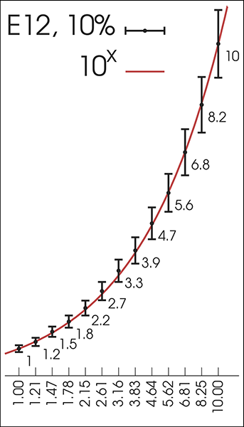
> […] Continuing this trend, rounding as needed, and we end up with the series 10, 15, 22, 33, 47, and 68. Components built to the E6 standard have a 20% relative error tolerance, and if we look at the values again we’ll see a trend. Starting with 10 again and adding 20% error we end up with 12. Moving to 15 and subtracting 20% we get… wait for it… 12. Moving up from 15 we get 15 + 20% = 18 and 22 – 20% = 17.6. This trend repeats no matter what range of powers of 10 you use, as long as they are consecutive. So 47kΩ + 20% = 56400, while 68kΩ – 20% = 54400.
> Look again at the values 47 and 68. The max/min values overlap right about 56, don’t they? That sounds familiar. The E12 standard uses all of the same values as E6, but with 6 more values mixed in. These 6 additional values are roughly where the E6 values overlap, and now in order to cover the entire range our %-error is reduced to 10%. Starting again at 10, we have 10, 12, 15, 18, 22, 27, 33, 39, 47, 56, 68, and 82. The math holds true here as well, with the error values just slightly overlapping.
It's the 'tolerance overlap' concept that makes the numbers work, but I don't think I've ever seen it explained so clearly before.