OpenSCAD is _awesome_ for targeting 3D printers, though.
Hint: 32GB of memory is not enough.
How did you try to learn FreeCAD? It took me quite a few tries to get the hang of it, but it is super powerful once it starts to click.
The "Part Design" workflow is best, in my opinion. Set workbench to "Part Design", create a "body", create a "sketch" on one of the xy,xz,yz planes, and then draw rectangles, circles, line segments, arcs, b-splines, etc. in the sketch. Constrain it using the constrains, pad it into a solid shape of a given width, then click on a surface on the solid and create a sketch on that surface, again draw the sketch and constrain it, and then you can either create a pad out of that surface, or a pocket into it, and so on. Once you're done, select some edges that you want to tidy up and either fillet or chamfer them, and the part is done.
You can also add or remove material by creating another sketch on one of the base planes and adding a new pad or pocket, or by revolving a sketch around a construction line. You can create "datum planes" in space to allow you to create sketches on planes that don't actually exist as either base planes or surfaces in the part. And you can add a linear pattern to duplicate a feature in a straight line, or a polar pattern to duplicate it in a circle, or a multitransform pattern to combine several of these. The Part Design workbench is really powerful.
There are some good tutorials on YouTube, but make sure you're watching "Part Design" tutorials. The older "Part" workflow is almost useless in comparison, it's basically the same as what you can do in OpenSCAD except without the programmability.
The worst part about FreeCAD is that sometimes if you ask it to do a complex operation (e.g. a fillet on some weird geometry), rather than just saying it can't work out how to do it, it segfaults.
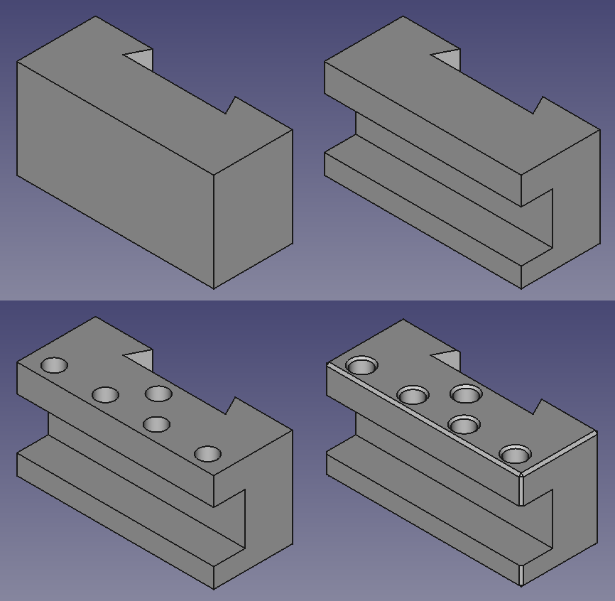
This GIF shows a simple part I recently made in FreeCAD: https://incoherency.co.uk/blog/cad-dojo/img/lathe-tool-holde... - It starts out with a sketch that is basically a rectangle with a dovetail cross-section cut out of it, padded up into a solid. Then a new sketch is created on one end with which to cut out the rectangular slot, and then a sketch is created on top to cut out holes to the required depth, and then some of the edges are chamfered.
In Fusion360, you can create global variables/parameters, calculate new values from them, and reuse them across parts. I haven't found any equivalent "central configuration" ability in FreeCAD, which is pretty important to my workflow.
For example you could create a cell called "cylinderbore" and have either a static value in it, or a value computed from something else, and you could set a radius constraint to "cylinderbore/2", or "cylinderbore/2 + 0.3" or whatever you want.
There's a demonstration in this 5-minute video: https://www.youtube.com/watch?v=b07qbhYHZbU
(Contrary to what the video implies, you don't have to manually click on each constraint whenever you change your spreadsheet, the global recalculate button will do it.)
For the central driving paramterss I recommend using a spreadsheet, as others have mentioned. I usually call that "inputs". And then have another one called "outputs" if I need to calculate something based on geometry, like total material/weights etc.
(I use Fusion too, and think it's overall easier to use and more polished, it just seems strange that the lack of parametricity is what irks you.)
And now using OpenSCAD feels like a chore, too much bruteforce coding.
FreeCAD has an OpenSCAD module and it makes for a really simple workflow of exporting your .csg files and importing them to FreeCAD. Both applications are scriptable, too, so with a little bit of bash and python you can automatically generate updated STLs and STEPs as you code in SCAD.
Being able to run both on an RPI4 maybe with curaengine would make a powerful little shop PC.
FreeCAD 0.17 release was dedicated to Roland Frank.[0]