Only one of the prongs carries power. The other is attached to the earth, and is always at zero volts.
> and then they will slowly switch places over the next 1/120 of a second so the right wire is at +170 volt
No. The power prong (the smaller one) will switch from -170 to +170. The other one (the neutral) is always at zero (measured relative to you).
> Turing three-phase voltage into two phase voltage is pretty easy. Just pick any two of the three wires and hook them into the home.
This is not what they do. If they did they would not be able to have a neutral, and you would also not have an option of 240v. Homes don't have two phases, they have split phase.
Instead they take a single phase, and attach it to a center tapped transformer, which I described here: https://news.ycombinator.com/item?id=16380133
> Just pick any two of the three wires and hook them into the home.
In actuality the phases have 240 volts between them, not 120. And from any phase to neutral is 208 volts (which some devices make use of). (Those are voltages to customers. Internally they use other voltages - in particular when they use a single phase, power a street with it - they care about the voltage to neutral, not the voltage relative to another phase.)
>> The electrical outlets in your home have two power-carrying prongs.
>Only one of the prongs carries power. The other is attached to the earth, and is always at zero volts.
Voltages are about potential differentials, so "zero volts" is relatively meaningless without context.
The neutral line is required by the electric code to be connected to earth at the electric panel, but even if it were not, any ungrounded appliances would work correctly.
Both prongs absolutely carry power. Slap an ammeter on the neutral line; it should be identical to that on the hot line. Don't actually do this, but if you were to cut the neutral line with a live circuit, you would see sparks. This is particularly important when working on circuits with a shared neutral (two hot lines on alternate halves of the split phase with a single neutral line); despite the breaker being off for your hot line, you can get shocked when working on junction boxes for the neutral line. Yes this is up-to-code in all states (though a few places either recommend or require ganging the circuit breaker when doing so).
>> and then they will slowly switch places over the next 1/120 of a second so the right wire is at +170 volt
> No. The power prong (the smaller one) will switch from -170 to +170. The other one (the neutral) is always at zero (measured relative to you).
Here you use voltages as a relative measure, which is correct. As a nitpick you do assume that the person is grounded. Walking on carpet in the winter, I can be at a potential of thousands of volts away from that though.
[everything from here after in ars's comment is correct and I have no more nitpicks]
Both carry current. But not power. Power is volts * amps, and the neutral is defined as zero volts (if you ignore the voltage drop).
> you can get shocked when working on junction boxes for the neutral line
Only from the voltage drop on that wire. It's not the full 120v. (Unless it's cut of course, but that's a whole different story.)
> Here you use voltages as a relative measure, which is correct.
First you introduce the concept, then later, explain other less important details. And that's how I wrote it.
> Walking on carpet in the winter, I can be at a potential of thousands of volts away from that though.
It's a good nitpick :)
Obviously voltage is relative. So I'm measuring with respect to me. With respect to me the hot has power, and the neutral doesn't.
i.e. If I attach a light bulb between me and either of the two electrical wires, will it light?
But you're right "carrying power" is a poorly defined term. The problem is that it's hard to use a term that is both clear, and strictly correct.
What he has already pointed out is that voltage is a relative unit. Zero volts by itself is meaningless. It would be just as correct to say that the hot wire is at zero volts and the neutral wire and the rest of the planet are at 120VAC. Also earlier you mentioned that from phase to phase inside a house was 240v but phase to ground was 208v. This isn't correct and it's simple trigonometry to prove why. You can visualize voltage potential in any polyphase AC system as the distance between points on a circle. Ground is the center of the circle and the individual phase is a point on the circle offset by the phase angle. For a split phase system there is 180 degrees between the two phases and cos(0) - cos(180) gives you the fairly obvious distance of 2x the radius. This means for 120v from phase to ground you get 240v phase to phase. In a three phase system there's 120 degrees between phases so if you have 120v from phase to ground you have (cos(0)-cos(120))*120v=208v. For what you're saying to be possible you would need 98.85 degrees between phases which is obviously not a nice integer division of 360 degrees.
"Electric power in watts produced by an electric current I consisting of a charge of Q coulombs every t seconds passing through an electric potential (voltage) difference of V is
P = work done per unit time = VQ/t = VI
Note that V is the "electric potential difference" and it take two conductors to supply power.
Only if something were actually drawing moderate current to cause the arc. But yes, one side of that cut is likely to end up "hot" and could give you a decent shock.
(How many levels deep can we nitpick here...)
I'm not buying this (in the USA). I've been in my breaker box. For a typical 110 volt outlet, the black (hot) wire is connected to the breaker, which is connected to one of the wires coming into the house from the street. The white (neutral) wire is connected to the same ground bracket that the bare (ground) wire is connected to.
240 volt connections (like my dryer and range) are taking a hot line from one of the lines coming into the house and another hot line from the other line coming into the house. You can see it on the bus bars in the breaker box. That's why dual breakers are used. Adjacent breakers pull for different bus bars.
*edit typo
In a breaker box, one wire (white) gets tied to ground, and the other wire (black or red) goes between +170 (relative to ground) and -170 (relative to ground). The black and red wires are 180 degrees out of phase, so when the black wire is at +170, the red wire is at -170. This gives a 340V peak difference between the black and red wires, which averages to 240V. You get your normal 120V outlet power between the hot legs and ground/neutral, and you get your 240V dryer & water heater power between the two hot legs themselves.
So, in a normal outlet, we can safely say that one wire is "more positive" than another, and that this flip-flops through time. When we look at voltages relative to ground, though, one wire stays put at 0V while the other goes between +170 and -170. It's just a question of where you put your reference frame.
In Europe, you have three phases (R,S,T) and neutral. Here the diff between any phase and neutral is 250V, and the diff between any two phases is 380V.
Is that everywhere, to every building?
In the USA, of necessity, power generation is three phase, large scale power distribution is three phase. What's confusing is that the previous discussion didn't differentiate between residential and commercial.
In USA residential areas nobody gets all three phases to their house or apartment. As discussed in previous comments, a house gets two hot wires and a neutral. In fact, to save money, sometimes entire neighborhoods only get one or two phases[1]: "spur lines" branching off the main line to provide power to side streets often carry only one or two phase wires, plus the neutral
In commercial and industrial settings it's common and necessary to deliver all three phases to the building. E.g. large electric motors require all three phases.
[1] https://en.wikipedia.org/wiki/Utility_pole#Power_distributio...
It is true that the voltage between live and neutral changes sign, so neutral is sometimes 170V above live. But neutral is almost always at ground, and live goes to -170V relative to ground.
That last paragraph though seems wrong, so OP may have been confused himself when writing.
Grounding to earth itself mainly serves to hold the potential of your house near that of the pole.
The best explanation of why three I was ever given hinged on "it's the number-of-phases argmin for the needed volume of wiring".
[1] two phases in quadrature, which is very different from split phase, which is not two phase at all.
I tried to word my explanation as accurately as I could, but I had to leave out a lot of tricky details for people who aren't electrical engineers. You have to be careful not to mix up regular averages, RMS averages, and instantaneous values when you deal with AC. If you get them wrong, you come to incorrect conclusions, such as the idea that single-phase electricity has zero power. The average voltage is indeed zero, but you can't use regular averages when you calculate power delivery, only instantaneous voltage differences and currents. You get RMS averages when you integrate those instantaneous values over time, and that brings in the the cos(phi) issues you mention.
In some places though, (I know it's common in New York, and also in a lot of datacenters), they do something like you describe, and hook 2 phases of a 3 phase system together. Since these are only 120 deg out of phase from each other instead of 180 in the split-phase system, you get less voltage, specifically 208V.
Under normal circumstances, the "hot" and "neutral" forms a continuous loop. But the pump that moves the water is connected to the "hot" hose. It alternates between pushing water out and sucking it back in. The "neutral" hose comes back from whatever is using the water and empties out into the tank that the pump uses as its water supply.
As long as the loop stays intact, anything the pump pushes out to hot will come back around in the neutral and get dumped back into the tank. Anything the pump sucks out of the hot will come back around from the neutral and get sucked out of the tank.
If you cut the neutral hose, the hot hose can still work, but only if you have a water reservoir at the other end big enough to accommodate a complete cycle of pushing and pulling. The pump operator doesn't like this too much, because it makes them reliant on customers to keep their water tanks in good condition, and if one gets damaged out there, the pump can't work as efficiently, and it could get damaged too. It's just safer for them to provide a second hose back to their own water tank.
But if you cut the hot hose, breaking the loop, neutral's got nothing. The water in it just sits there. This is where the ground hose comes in. It is also shoved into the water tank at one end, same as neutral. It's sole purpose is to complete a loop back to the water tank in case the regular loop fails, so that water doesn't spray too far or let air get into the pump. Ground is the emergency backup return path.
Connecting electrical wires to a ground rod pounded deep into the earth is like sticking the loose ends of your hoses in the ocean. You can pull as much water out of it as you need, and dump as much into it as you need. Sea level stays the same.
The generator at the power company has 3 stators that are on equal distance between each other on a circle. As the rotor rotates, it induces AC voltage at each of them.
Because the rotor rotates at a stable speed, the AC voltage follows a sine function.
Because the stators are placed 2/3pi apart, their sine waves have a phase difference of 2/3pi.
Because 2/3pi+2/3pi+2/3pi=2pi, if you add them all together then you get 0 (sin[2pi]=0) and this is your neutral wire.
Quite honestly I learned that very late in the university which is a pity. Once you see how the real world translates to math, many things (like euler's formula which is of utmost importance for engineers) fall in place.
Incidentally, the closely spaced multiple wires within each conductor of an electrical transmission line, typically held apart by spacers, act to reduce the inductance of the transmission line, which reduces losses. The little "dumbbells" which are on each side of each tower, are vibration dampers to reduce metal fatigue.
The one-way plug ensures that the "hot" voltage stays in the wall when the device isn't on, so if you shove your wand into a toaster that's off you won't get electrocuted. Devices are always connected to neutral, and the switch connects them to hot.
Your standard 120V appliance outlets are only using a single phase and neutral. IIRC the smaller prong is hot and the larger prong is neutral.
https://i.redd.it/bm1gqw8hzppz.jpg
Of course that's an ungrounded plug so they're in trouble either way, but you get the idea.
Another option (which I've never seen in the US) is plugs where the first chunk of the line/neutral prongs are insulated:
http://www.liddellappliancetesting.co.uk/ESW/Images/insulate...
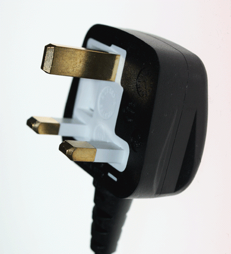
Someone put a lot of thought into the design. Ground at top to prevent accidents like you show. Ground pin is longer. Insulation covers enough of the pins that live and neutral disconnect before conductor is exposed from socket. Both will be fully disconnected before earth disconnects.
If you actually look at a NEMA 5 outlet with the ground pin compared to old ungrounded polarized NEMA 1 outlets the NEMA 5 outlet is rotated 180 degrees. The larger neutral slot is on the right on old outlets and with the ground pin down on a NEMA 5 outlet the neutral is on the left.
It's not just for people dropping coins or paper clips on it though. Some outlet covers are metal and if the screw is loose or damaged that's basically guaranteed to short out if something is plugged in with the ground pin on the bottom. Another common thing is people using a tape measure along a wall, it's so thin that if there's a small gap it could shock someone using it or if you're lucky just short against the neutral.
hot has black insulation, neutral white
hot wire insulation will be smooth, neutral ribbed
hot terminal screws will be brass, neutral silver (chrome)
The neutral side is connected to the ground. (Literally - they stick a metal pole in the ground.)
The 3rd wire, is also attached to the ground, and in the electrical box the two wires are attached together.
Anyway, that's why it's neutral - because it's attached to the ground, so it's at the same potential as you.
“Isn’t quite how it works” is a gross understatement. I apologize, but while there’s some correct facts, the entire narrative you spun clearly shows you don’t have the first clue what you are talking about. I really want to be as polite as possible, but what did you expect to accomplish by posting this?
The electrical outlets in your home have two power-carrying prongs. The third prong is just for safety (it connects to the ground), and should never carry power unless something is going horribly wrong. In that case, the power should hopefully prefer to reach the ground through that third wire than through your human body.
Anyhow, the voltage in those two power-carrying wires is constantly switching directions. At one moment, the left wire will be +170 volts relative to the right wire, and then they will slowly switch places over the next 1/120 of a second so the right wire is at +170 volts. They continue trading places, completing a cycle every 1/60 of a second.
At some point in this cycle, the voltage difference between the two wires will be zero, which means that no power will be flowing at that moment (power = voltage * current). On the average, the wires will deliver the same amount of power as-if they had a constant 120 volts between them, which is why people say that electricity in the USA runs at 120VAC. The peak-to-peak voltage is 170V, but the "RMS" average voltage is 1/√2 of that, or 120V.
Anyhow, those brief moments of time where no power is flowing are a problem for a power company, who would like to deliver energy in a continuous stream. So, they build their power system with three wires. Each wire reaches its maximum voltage 1/180 of a second after the previous wire. Since the voltages on each wire are sine waves, when one wire is at 0, the other wires are at +√3/2 and -√3/2 of their maximum voltages. Therefore, there is no point where the power stops. In fact, due to a mathematical quirk, the power delivery is actually constant, even though the voltages on the three wires are constantly changing.
Turing three-phase voltage into two phase voltage is pretty easy. Just pick any two of the three wires and hook them into the home. The difference of any two sine waves is just another sine wave at the same frequency, so you automatically have single-phase power. In practice, the power company will try to balance the load between the three pairs of wires by sending different pairs into different houses or even neighborhoods.
Edit: As several people have pointed out, this isn't quite how it works in real life. See the comments below for details about the hot vs. neutral wire and how both 240V and 120V are available in the home at the same time.